Secondary Cage
The foam cage
Del has far more experience with building things than I do. In
particular, he has a lot of experience building things that need to be
strong and light. Still, the secondary cage he built for his 8"
scope out of pink Styrofoam, epoxy and wood veneer completely shocked
me. It is far stiffer than I ever would have guessed. It looks
beautiful and is really light. So I was thrilled when he offered to
build one for me.
Del cut the foam with a hot Nichrome wire. Apparently it is tricky
to get the wire hot enough to cut the foam without making it so hot
that the wire melts. He managed to produce 5 rings though that were
18.5" O.D. and 16.5" I.D. and 1.5" tall. He then
epoxied the rings one on top of another to create the 7.5" tall
cage. I was really lucky that the scope's design required the
secondary cage to be an even multiple of 1.5" tall rings,
otherwise I don't know how we could have a made a good flat cut to
make it shorter.
Del spent a fair amount of time sanding the foam smooth. He also
epoxied in some small foam bits and blocks to fill in any voids that
resulted from flaws in the foam or any cutting mistakes made along the
way.
The next step was to build in hard points. These fall into three
categories. The first is the hard points for the focuser. Next are
the connections for the truss tubes. Finally there are the hard
points for where the spider attaches.
 For the focuser there were actually 4 separate
hard points, one for each of the focuser's mounting screws. They were
made out of a stiff lightweight wood Del found. Rather than cut them
directly into the rings, he made a small foam block to work with that
is the size of the focuser's footprint. He then sanded the underside
so it would match the curve of where it would fit into the rings. He
left the top flat to match the flat base of the focuser. Bringing the
focuser an extra 1/8" closer to the secondary mirror was a nice
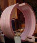
fringe benefit of this. The photo shows the rings glued together. At
the bottom of the rings is the inset piece to be used for the focuser
hard points.
 Del had Dick mill the hard points for the truss
connects were from aluminum and he did an amazing job. They more or
less made to match one of the designs suggested by Kriege. Total
weight for the four hard points with triangular wedges and screws was
almost exactly a pound. We could have made these lighter, but time
was running out and we figured we had saved enough weight that it
wouldn't be too big a problem. The photo shows the hard points in
place for the truss tubes and focuser.
The hard points for the spider were just 2" square blocks of
1/8" thick aluminum. They probably didn't need to be quite this
big. I wanted to leave them a bit large though for two reasons.
First, I was told that the spider would need a lot of tension on it
because its veins are only 3/4" wide. Big hard points spread
that force out over a larger area. The other reason is that if I ever
had to replace the spider, I would have lots of room to drill new
holes for the new spider mount points. Del also ran a strip of thin
fiberglass cloth around the cage at this end to improve rigidity and
strength.
Del learned a lot during the construction of the cage. The first
thing he found out is that the wood needs to be kept isolated from
moisture. This lesson was learned on a previous project where he
epoxied the veneer over cardboard. Even though the veneer was
varnished, moisture in the air crept in through the cardboard.
Eventually the veneer rippled, buckled and peeled off.
The strength of the foam/veneer cage is dependent on the composite
effect, which in turn depends on the veneer being attached securely to
the foam. So the buckling wasn't just unsightly, it was a serious
structural problem. This setback in the prototype turns out to have
foreshadowed the demise of the foam cage concept.
Applying the veneer to the cage was difficult work as the birch
veneer tended to crack and split. Cutting it to size was a problem
only made worse by the demands of the epoxy. After applying most of
the veneer to the interior of the Miatascope's cage, Del was pulled
away from that project for a couple weeks. Before he came back to it,
moisture in the air got to the unvarnished veneer, which then rippled
and buckled.
At great effort and with only a few days left to go, Del removed
all that difficult work and did it again. This time he did the work
in a room with a dehumidifier and immediately applied varnish to the
veneer after the epoxy had dried.
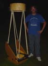
 Here I
am standing next to the scope at first light including the nearly
finished foam secondary cage. In bringing the cage to this point, Del
learned a few lessons. He found that there were voids where the
veneer wasn't fully glued to the foam rings. He said that this was a
big enough problem that for the interior of the cage it probably would
have been better to just use fiberglass instead of wood veneer. Since
the plan was to cover the interior of the cage with flocked paper
anyway, there was no need to make it pretty. And of course, there
were also the serious problems with using birch for the wood
veneer.

 Del finished the work in
time for first light. The triumph of this accomplishment turned to
tragedy though. The evening of first light the dew was among the
heaviest I have ever seen. Everything brought outside came back in
with water everywhere. After only a couple hours of exposure to this
environment, the veneer on the foam cage was already coming off the
foam in a very noticeable way.
We hoped that the problem was due to moisture leaking in through
the uncovered foam ends of the cage. Those hopes were dashed though
when we noticed that another cage Del made earlier for an 8"
scope was having the same problem even though it was fully varnished.
The foam secondary cage concept would have to be abandoned, and there
was only a week to go before Astrofest.
The Kriege cage
We so little time remaining, I decided to go with a secondary cage
built the way Kriege and Berry suggest. Thankfully it turned out that
this cage design is very simple and easy to make. I was amazed when I
weighted the end result and discovered that it was close to the same
weight as the foam cage would have been.
There were some construction issues though that could have gone
better. The first was the cutting of the rings for the cage. I
failed to mark where to drill the indent holes for the aluminum tubes
between the top and bottom rings. I couldn't figure out how to get
four points 90 degrees apart. The absence of the material in the
center of the rings complicated things a lot more than I ever would
have guessed. I wanted to be sure that they really were
exactly 90 degrees apart so I would only get 4 diffraction
spikes off the spider instead of 8. To solve the problem I ended up
buying more wood, marking where the holes would go and cutting two new
rings.
Later I discovered that I should have trusted a suggestion of
Del's. He recommended that I wrap a strip of paper around the
perimeter of a ring, fold it in half twice and mark on the ring the
location of the four folds. Turns out that is the technique Kriege
recommends. And then I read H. R. Suiter's remarkable book,
"Star Testing Astronomical Telescopes". In it he said that
8 weak diffraction spikes could in some ways be better than 4
strong ones. Precious time and beautiful wood wasted for naught.
The second thing to be pointed out in the secondary cage is the way
the aluminum spacer tubes are connected to the rings. Kriege suggests
using "threaded inserts". I didn't find a source for them
until after the scope was done (the answer is to try a bicycle shop).
My uncle Alex though had a suggestion that saved the project. He
recommended using a dowel rod inserted in the aluminum tubes and
attached to the rings. Grandpa, in true child of the great depression
fashion, then took me to his basement where his large collection of
old broom handles resulted in finding one that perfectly fit inside
the aluminum tubes.
I cut 4 x 2 = 8 dowel rod bits about 2" long. I attached the rings
to the dowel rods using glue and wood screws. The screws were mostly
to hold the dowel rods in place while the glue dried. I then put the
aluminum tubes over the dowel rods and drilled holes through the
aluminum and dowel rods.
This technique helped me shrink the overall height of the cage.
That is because there were no bolts for the threaded inserts to get in
the way of the two sets of bolts that had to go through the tubes.
The first set of bolts is on the top end of the cage to attach the
spider. On the bottom end of the cage are the bolts that hold the
latches to the tubes.
 Which brings me to
one of the unique features of my Miatascope that I am proudest of.
The cage attaches to the truss tubes by using latches like one would
find on a trunk. These latches attach to woodblocks at the top of the
truss tubes. To keep the woodblocks in the right place on the rings,
wood screws protruding down from the bottom of the bottom ring go into
divots in the woodblocks. The screws and divots keep the rings from
sliding off the woodblocks and the latches keep the screws in the
divots.
Naturally, there were some concerns that this solution would not
work. Turns out though that everything works great. There is no
problem with the cage moving. It doesn't even wiggle a little. It
attaches very quickly and easily. I like this solution better than
any other solution I've seen.
 Because the
secondary cage is so short, I needed an extension to the cage to block
stray light. I originally made two Formica light shields. They
attached to the cage with Velcro and when rotated 180 degrees were
reattached to outside of the cage for easy transport. Too bad these
light shields were too small. So I tried a taller two piece shield
that blocked the light, but was hard to transport.
 So now I
use a three piece version that extends 12" beyond the top of the
cage. It is made of black plastic, which are again held on with
Velcro. Each piece of plastic goes a third of the way around the
cage. I was fortunate to be able to find suitable plastic at a small
neighborhood shop that makes signs. The stray light problem I had is
gone, and the pieces are short enough for me to carry them in my bag
with the side bearings.
Back to the Miatascope home page.
Last updated 1/12/06
 For the focuser there were actually 4 separate
hard points, one for each of the focuser's mounting screws. They were
made out of a stiff lightweight wood Del found. Rather than cut them
directly into the rings, he made a small foam block to work with that
is the size of the focuser's footprint. He then sanded the underside
so it would match the curve of where it would fit into the rings. He
left the top flat to match the flat base of the focuser. Bringing the
focuser an extra 1/8" closer to the secondary mirror was a nice
fringe benefit of this. The photo shows the rings glued together. At
the bottom of the rings is the inset piece to be used for the focuser
hard points.


