Mirror cell
Scope construction is supposed to start with the secondary cage,
but I started with the mirror cell anyway. This is because it
required metal work and was therefore the one thing I couldn't do by
myself. Fortunately, I knew that Del was on the lookout for metal
working opportunities and was eager to help out.
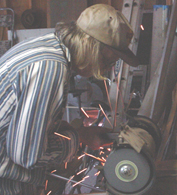
 We
started with the triangles that support the mirror. We cut them free
hand on a band saw. This probably wasn't the best way to do this, as
we didn't cut them as accurately as planed. To fix the problem, Del
spent a lot of time grinding them to make them all the same size. All
that effort hurt all the more when I decided later to drop them when I
switched to using the triangle dimensions specified by Cell instead of
Plop.
We
started with the triangles that support the mirror. We cut them free
hand on a band saw. This probably wasn't the best way to do this, as
we didn't cut them as accurately as planed. To fix the problem, Del
spent a lot of time grinding them to make them all the same size. All
that effort hurt all the more when I decided later to drop them when I
switched to using the triangle dimensions specified by Cell instead of
Plop.
The sides of the mirror cell were also cut free hand on the band
saw. Since tight tolerances were not really an issue and we had
already practiced on the triangles, we did pretty well on these. A
bit of draw filing later on made everything fairly consistent and took
off the rough edges.
 Del's band saw is able to rotate into a position that made it
easy to cut the square, steel tubes for the rungs of the ladder. Once
we had all the parts cut, we put them into position and held them in
place with some special welding magnets. We measured and adjusted
things over and over again before we realized that one of the square
ladder rungs was too long and needed to be ground it down a bit. That
really helped and the next series of measurements and adjustments went
much better. Del did one measurement that really helped the final
result. It was to check the diagonal distances between the corners of
the mirror cell. When they weren't the same, we knew there was a
problem somewhere.
Del's band saw is able to rotate into a position that made it
easy to cut the square, steel tubes for the rungs of the ladder. Once
we had all the parts cut, we put them into position and held them in
place with some special welding magnets. We measured and adjusted
things over and over again before we realized that one of the square
ladder rungs was too long and needed to be ground it down a bit. That
really helped and the next series of measurements and adjustments went
much better. Del did one measurement that really helped the final
result. It was to check the diagonal distances between the corners of
the mirror cell. When they weren't the same, we knew there was a
problem somewhere.

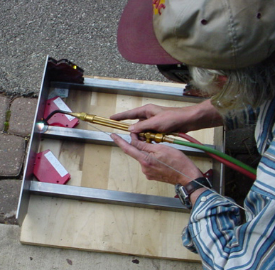
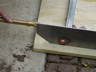
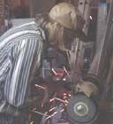
 Welding turned out to be kind of
difficult. The big square tubes being welded to the flat steel plates
of the sides could soak up a lot of heat. This made it difficult to
get the spot we were welding hot enough to get a good weld without
melting through the steel. Needless to say we were successful and I
even was able to try my hand at one of the easier welds.
Welding turned out to be kind of
difficult. The big square tubes being welded to the flat steel plates
of the sides could soak up a lot of heat. This made it difficult to
get the spot we were welding hot enough to get a good weld without
melting through the steel. Needless to say we were successful and I
even was able to try my hand at one of the easier welds.
I am delighted with what we ended up with. The ladder is square.
Just as important, it is strong enough for someone to stand on. It
looked even better after it got a coat of primer to keep the rust off.
Del also went back later and brazed the seams we didn't weld to
provide extra water protection.
After the welding was done, we drilled the holes we needed. Kriege
and Berry recommend doing this before the welding. Del determined
that his drill press could clear the assembled cage though so we
welded first. Manipulating the whole cage under the drill press was a
bit awkward at times. It was nice to not have to worry about part
orientation during the pre-weld assembly stage though.
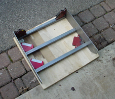
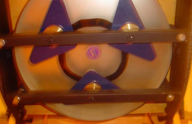
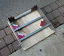
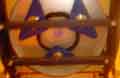
 We then
handed the ladder off to Del's friend and metal working mentor, Dick
for some additional work. Del was worried about the lack of a good
chunk of steel to thread for the collimation bolts. So Dick welded
into the square tubes some 3/4" long threaded inserts for the
bolts to grab on to. The picture here shows the work at this stage.
The mirror cell with the triangle mirror supports based on the output
from "Plop" can be seen.
We then
handed the ladder off to Del's friend and metal working mentor, Dick
for some additional work. Del was worried about the lack of a good
chunk of steel to thread for the collimation bolts. So Dick welded
into the square tubes some 3/4" long threaded inserts for the
bolts to grab on to. The picture here shows the work at this stage.
The mirror cell with the triangle mirror supports based on the output
from "Plop" can be seen.
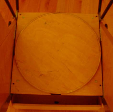
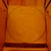
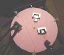 To get a better
idea of how things would fit, we made a mock up of the mirror out of
the same foam we wanted to use for the secondary cage. After cutting
the rings for the cage, we had plenty of scrap that could easily be
trimmed down to 15" in diameter. The material is 1.5" thick
and the mirror is 1 5/8" thick, so the disc was never going to be
an exact replica and didn't worry about making the edges smooth. The
picture shows the mirror cell with the mirror mockup in place. Since
the cell has been coated with black primer at this point, it is kind
of difficult to make out in this shot. Sitting on the mock up of the
mirror are the hard points we were going to use to attach the truss
tubes to the foam secondary cage.
To get a better
idea of how things would fit, we made a mock up of the mirror out of
the same foam we wanted to use for the secondary cage. After cutting
the rings for the cage, we had plenty of scrap that could easily be
trimmed down to 15" in diameter. The material is 1.5" thick
and the mirror is 1 5/8" thick, so the disc was never going to be
an exact replica and didn't worry about making the edges smooth. The
picture shows the mirror cell with the mirror mockup in place. Since
the cell has been coated with black primer at this point, it is kind
of difficult to make out in this shot. Sitting on the mock up of the
mirror are the hard points we were going to use to attach the truss
tubes to the foam secondary cage.
These trial assemblies made it easy to see some problems that
needed to be solved. The biggest was that the bolts for the
collimation triangles were going to make the overall mirror cell too
tall. We caught a bit of luck here though.
 I originally planned on having the collimation
knobs on the bottom of the cell. By moving them inside the cell,
above the square tubes of the ladder rung and just under the mirror,
we were able to save the height of the knobs and the length of the
bolt travel from the over all height of the cell. In addition, Del
threaded the collimation knobs and suggested we use them as the lock
nuts for under the triangles in the cell. This saved the height of a
nut (1/4"). Since the total cell height is only 4 3/4",
saving this space was really critical. Doing this would have been
impossible without the 3/4" inserts Dick suggested.
I originally planned on having the collimation
knobs on the bottom of the cell. By moving them inside the cell,
above the square tubes of the ladder rung and just under the mirror,
we were able to save the height of the knobs and the length of the
bolt travel from the over all height of the cell. In addition, Del
threaded the collimation knobs and suggested we use them as the lock
nuts for under the triangles in the cell. This saved the height of a
nut (1/4"). Since the total cell height is only 4 3/4",
saving this space was really critical. Doing this would have been
impossible without the 3/4" inserts Dick suggested.
It was around this time that Del got seriously excited by brazing.
While a braze is not as strong as a weld, it is still a very
strong connection. Welding works by melting two pieces together. It
is strong, but can warp the pieces a bit. Brazing is closer to
soldering. It isn't as strong, but since the pieces being brazed
together aren't melted, they don't deform.
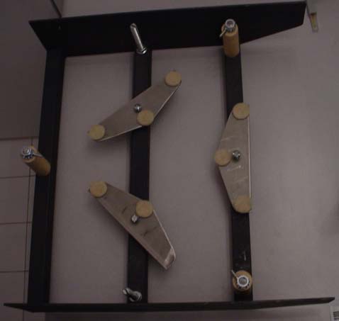
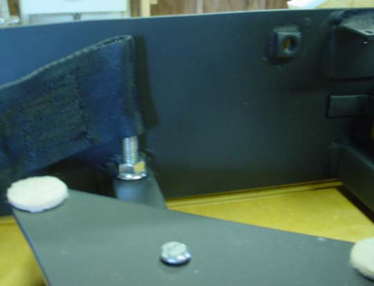
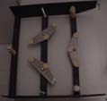
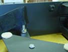 The side bearings are attached directly to the mirror cell using
some bolts that have big knobs on them. Where the bolts attached to
the mirror cell though, there really wasn't enough metal for the bolts
to grab on to. So we drilled holes in the sides of the mirror cell.
Then Del brazed nuts behind the holes. Doing this involved a fair
amount of technique created by Del on the fly. He started by using a
bolt threaded into the nut and placed in the hole of the side bearing.
He did this to keep the nut from moving relative to the hole as the
brazing was done. This also kept the brazing material away from the
threads in the nuts. He then tacked the nut in place by brazing just
a dot in the corner of the nut. He let things cool a bit, but before
the braze went cold he removed the bolt. After this he finished
brazing around the nuts. Those nuts aren't going anywhere. The
picture shows some of the interior detail of the mirror cell at this
stage. Note the nuts for attaching the side bearings and the right
angle piece for attaching the baffle.
The side bearings are attached directly to the mirror cell using
some bolts that have big knobs on them. Where the bolts attached to
the mirror cell though, there really wasn't enough metal for the bolts
to grab on to. So we drilled holes in the sides of the mirror cell.
Then Del brazed nuts behind the holes. Doing this involved a fair
amount of technique created by Del on the fly. He started by using a
bolt threaded into the nut and placed in the hole of the side bearing.
He did this to keep the nut from moving relative to the hole as the
brazing was done. This also kept the brazing material away from the
threads in the nuts. He then tacked the nut in place by brazing just
a dot in the corner of the nut. He let things cool a bit, but before
the braze went cold he removed the bolt. After this he finished
brazing around the nuts. Those nuts aren't going anywhere. The
picture shows some of the interior detail of the mirror cell at this
stage. Note the nuts for attaching the side bearings and the right
angle piece for attaching the baffle.
I needed a cover for the mirror to protect it from damage when the
mirror cell is in transit and storage. I planned a two-part solution
consisting of a baffle and a dust cover for the hole in the baffle
when the scope is not in use.
To hold the baffle in place, Del brazed on a bit of steel bent at a
right angle. We then drilled and tapped holes to screw the baffle
down to. Conventional corner reinforcement pieces normally used in
woodworking were also brazed on as mounting points for the plastic
dust covers for the front and back ends of the mirror cell.
During design I realized that some sort of "handles" were
going to be needed so I could pull the mirror cell out of the trunk.
Given the lack of height for proper handles, I planned on using some
rope instead. The idea was to tie the rope to holes in the same bits
of angled steel used to hold the baffle in place.
So far in actual use though, the rope hasn't been necessary.
Originally I didn't put it because I wanted to maintain easy removal
of the baffle while tweaking the mirror and cell. Later, I realized
that my habit of picking up the mirror by reaching in to the cell and
lifting the cell from the angled steel worked just fine. This looks
like it will be the final answer for how to lift the cell.
I would like to point out that a lot of metal detail work was done
on the mirror cell. This is because the mirror cell doubles as my
mirror box. Since I no longer had wood to work with, all the woodwork
that normally would have been done for things like the baffle became
metal work instead.
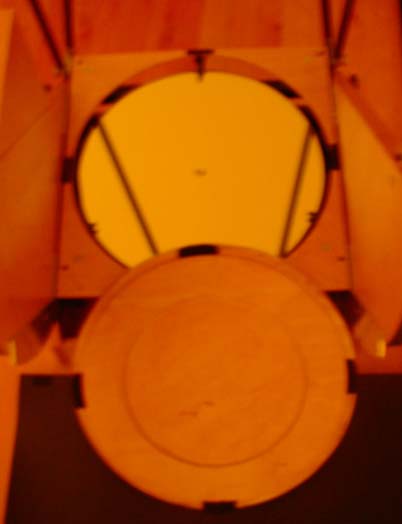
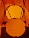 As for the dust cover for the hole in
the baffle, this was made more or less the way Kriege suggests.
Ideally, I should have the inner reinforcing ring a bit bigger so it
fit the hole a bit tighter. The real problem with my wooden dust
cover though is that it can touch the mirror if the cover gets hit the
wrong way. This has to do with how little clearance there is between
the baffle and the mirror.
As for the dust cover for the hole in
the baffle, this was made more or less the way Kriege suggests.
Ideally, I should have the inner reinforcing ring a bit bigger so it
fit the hole a bit tighter. The real problem with my wooden dust
cover though is that it can touch the mirror if the cover gets hit the
wrong way. This has to do with how little clearance there is between
the baffle and the mirror.
I am not certain yet how I will deal with this problem. For now I
have reduced the potential for this to cause damage to the mirror by
covering the edge of the cover with a plastic tube that has been split
lengthwise. In the future I may end up replacing the cover with a
square sheet of Formica that covers both the hole in the baffle and
the baffle itself. The wood circle with plastic tubing around the
edge is looking pretty permanent at this point however.
After a couple years I eventually added a muffin fan to cool the
mirror. I did attach it with some elastic string loosely wrapped
around the ladder rungs. The plan is that the elastic string will
help isolate fan vibrations from the rest of the scope. Unfortunately
I haven't tested this in field yet. Not because I've not noticed
cooling issues. I have. Nope, the problem is I keep forgetting that
I put in a cooling fan.
To power the fan, I mounted a 9v battery in a metal clip from Radio
Shack. The clip is attached to one of the unused screw holes I put in
the mirror cell to hold a baffle I never installed. I was going to
run wires from the fan up to the secondary cage to power accessories
up there. In the end I decided that the weight of the battery wasn't
much more than the weight of the wires and the annoyance of hooking up
wires during setup was more than I wanted to deal with.
Back to the Miatascope home page.
Last updated 1/12/06
 We
started with the triangles that support the mirror. We cut them free
hand on a band saw. This probably wasn't the best way to do this, as
we didn't cut them as accurately as planed. To fix the problem, Del
spent a lot of time grinding them to make them all the same size. All
that effort hurt all the more when I decided later to drop them when I
switched to using the triangle dimensions specified by Cell instead of
Plop.
We
started with the triangles that support the mirror. We cut them free
hand on a band saw. This probably wasn't the best way to do this, as
we didn't cut them as accurately as planed. To fix the problem, Del
spent a lot of time grinding them to make them all the same size. All
that effort hurt all the more when I decided later to drop them when I
switched to using the triangle dimensions specified by Cell instead of
Plop.