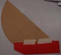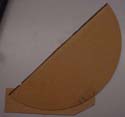
 The side bearings also affect how the mirror cell
clears the rocker box. The math for this got kind of hairy. So I
made this 1/2 scale model out of cardboard from an old shoebox.
Invaluable.
The side bearings also affect how the mirror cell
clears the rocker box. The math for this got kind of hairy. So I
made this 1/2 scale model out of cardboard from an old shoebox.
Invaluable.These are made from 1" thick Baltic birch plywood. I made the 1" plywood by gluing together 3/4" and 1/4" thick sheets. They have a large radius, even by Kriege's standards to make up for the short mirror box. A nice fringe benefit of making them large though was that I felt more comfortable about spacing the Teflon for the pads closer together. This aided in keeping the mirror cell short.
The bearings were a key bottleneck along the critical path for the scope's construction. This is because the radius of the bearing cuts is dependant on the location of center of gravity ("CG") of the scope. In order to do a decent job of calculating the CG, work had to get pretty far along on the mirror cell and secondary cage. Even when they were both almost finished though, I still found that I needed to make a large number of estimates. I hated to rely on estimates so much and wished I could have just weighed everything. Inevitably the point came where I just couldn't hold up the rest of construction any longer.
A rather elaborate spreadsheet to compute the CG was also very helpful as it let me try out different bearing sizes and see how clearance and balance would be affected. From it I learned that adding an inch to the radius of the bearings added about a pound to the weight I could add to the secondary cage.

 The side bearings also affect how the mirror cell
clears the rocker box. The math for this got kind of hairy. So I
made this 1/2 scale model out of cardboard from an old shoebox.
Invaluable.
Cutting the side bearings turned out to be lot of work and it took Del and I about 10 hours to get it done. Mostly because of "learning opportunities " we encountered along the way. First, it would have been much easier to have cut a single circular disk of the correct radius and then cut that disk into pieces than to try to use the scraps I had left over. The scraps were wide enough for the bearings, but not as wide as the radius of the cut. This introduced a whole family of problems.
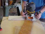
The other big problem with cutting the side bearings was doing the actual cut. One would have thought that after all the times Del suggested something and I told him he was crazy, I would have learned my lesson. Yup, one would think that. Del suggested we make a series of cuts, each a bit deeper than the one before it. In my head I had images of the curves of the side bearings looking Chinese terraced farms along a hillside. Fortunately he talked me into testing the idea out. To my surprise and delight the cut was perfect. I was even more surprised when I reread the section of Kriege and Berry where they said to use Del's multi pass trick.
 Even with Del's idea though, we still had problems. For reasons
still not fully determined, I smoked the router bit before we had cut
a single bearing. I think this was due to a number of factors. One
may have been that it was an old, dull router bit. Plywood has a lot
of glue in it, which contributed to the problem as well. We think the
biggest problem was that I cut too deep on my first cut. This caused
the wood to burn and carbon to collect on the bit. Subsequent cuts
just added to the problem as the extra carbon generated heat faster
leading to a vicious cycle. From time to time Del chipped as much
carbon off as he could with his pocketknife. In the end though, the
router ceased to generate any sawdust and instead was just producing
smoke. Those of you who know what you're doing with tools are
cringing I know - sorry.
A trip to the 24-hour Home Depot though meant I had 4 new bits to play with the next day. By limiting our cuts to 1/4" or less on each pass, we were able to do the full day's routing without damaging the new bit at all.
The day got off to a bad start though when we went to draw the cut on the second bearing using the bearing from the day before as our pattern. It turned out that my second piece of wood was a tiny bit narrower than the first. So I took advantage of the fact that the bearings were designed to be 1/2" oversized and made the radius of the cut 1/8" smaller.
 With the lessons learned from the day before, Del and I
were able to (re)cut both side bearings, the curves in the sides of
the rocker box for the bearings and cut the circles for the dust
cover/baffle. Best of all we got everything done in slightly less
time than our single (incorrectly sized) part took to cut the night
before.
In general one thing we learned that I cannot stress enough is to check, recheck and sanity check measurements in this area every way you can think of. Everything was checked against my calculated sizes. Cut parts were compared against parts to be cut. The router was moved along its expected path to see if we would "bottom out" again or miss precalculated marks. More than once a bad cut was saved at the last moment when "one last sanity check" revealed a problem. This was especially key when dealing with issues like how to account for the width of the router bit.
Grandpa did most of the work gluing of the Formica strips to the side bearings. Not only was it great to have an extra set of hands when working with long floppy pieces of Formica and contact cement, but he also had a suggestion that made life a lot easier later. I planned to just stick the extra wide Formica strips to the edges of the bearings and trim both sides of each bearing later. Grandpa had a big, clear(!) worktable for us to use though. So he laid the bearings on their sides and used the table to make sure one edge of the Formica matched up perfectly with the edge of the bearing.
When it was time to trim the bearings, Grandpa's technique turned out to be a real lifesaver. The bearings were too big to use the band saw to trim the Formica. So I used a router with a router table. Since I had one edge of the Formica that was already square and flush with the bearing, I could use the edge guide on the router table to hold the wood in position.
I also picked up a special laminate trimming router bit, which was a big help as well. This is different from a router bit that is rated to cut Formica in that it has a small roller bearing at the top of the bit. This bearing is exactly as big as the cut of the bit. This allowed me to squeeze the side bearing between the router table's edge guide and the roller bearing on the router tip. The resulting cuts were perfect.
Back at Del's shop, we drilled the holes to mount the side bearings to the sides of the mirror cell. Del saved the day by a quick spot check that revealed that the holes in the sides of the mirror cell were not lining up. We recut that hole and double-checked the other hole locations. It took a lot of time, but in the end we were both thrilled and relieved to see when we were done that the sides were square and lined up with each other perfectly.
Equally important was how ridged the side bearings were once they were bolted to the mirror cell. I was worried that I would need a cross brace to keep the side bearings from flopping around. Turns out that they are absolutely ridged. Not needing to use a cross brace also makes field assembly and transport that much easier.
The trial assembly of attaching the side bearings to the mirror cell did reveal one major problem though. That problem being how hard it is to get the screw holes in the side bearings to line up with the holes in the mirror cell. I solved this by using some bits of steel as guides to line things up. They aren't pretty, but they also are on the inside of the bearings and they were easy to implement.
 Later testing
revealed an additional problem. Normally the mirror box is tall
enough to keep the bearings in place. With my short mirror cell,
there are positions where the bearings can simply slide off the Teflon
pads of the rocker box. To prevent this from happening, we cut some
aluminum guides to place on the insides of the bearings.
Then we had to cut the notches into the side bearings for where the truss tubes attach to the side bearings. Del knew that there was a way to do this with a router, but neither of us could figure out how. I found the answer in a book on routing sold at Sears. The trick is to place the router guides outside the base of the router and make them bigger than the base by the size of the cut to be made. Del then squared up the corners with a chisel.
Back to the Miatascope home page.
Last updated 1/12/06