Truss Tubes
The truss tubes are 5/8" diameter carbon fiber
("CF"). I was able to have some custom made to 60"
long. Carbon fiber conducts electricity and someday I may use that
fact to run current from a battery at the base up to the cage to power
the dew heater and any other toys. While carbon fiber is extremely
ridged, the tubes will crush. However they are UV resistant, very
light and look nice without any finishing needed.
Each end of each truss tube has a peg in it. The lower pegs are
made out of aluminum. The top pegs are oak. All the pegs extend
about 3" into the truss tube and are held in place with epoxy.
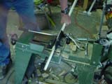
The part of the peg that sticks out from the tube is a half cylinder
that Del milled down. This flat part of the peg is then attached to a
truss connector.
The truss connectors on top are described in the section on the
secondary cage. The truss connectors on the bottom end fall into two
classes. There are the front connectors that attach directly to the
mirror cell. There are also the back connectors that attach to the
side bearings.
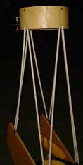
All of the truss tubes always remain attached to the truss
connectors. It is the truss connectors that are bolted or latched to
the top and bottom of the telescope during field assembly. During
disassembly, all the tubes come off in a bundle for transport. This
means that for assembly, the four connectors at the bottom are screwed
to the mirror cell/side bearings and the four connectors at the top
are latched to the secondary cage. This process is possible for one
person to do without assistance, having an extra set of hands though
to hold things in place does help though.
The final moment of panic and near disaster happened when I made a
mistake about how the truss tubes would be transported. The plan was
that they should collapse together in a bundle and go in the front
seat with the passenger. As things worked out, everything went to
plan. Less than a week away from Astrofest though I had a day where I
lost faith that the tubes really would fold together that way. In my
panic I nearly redid the entire bottom end connection system.
Fortunately, Del was able cope with my nasty mood and pull me back from
the brink before changes had been cut.
 The
front truss connectors are steel blocks that are attached to the front
corners of the mirror cell. These connectors are notched to make it
easy to feel where they go in the dark. They attach to the mirror
cell. Del also made some really beautiful knurled brass knobs for
these bolts.
 The
connectors that attach to the side bearings are aluminum blocks that
slip into the notches cut in the bearings. Del also cut the cool
knurled knobs for this end in time for Astrofest 2003 but not in time
for this photo.
Using different attach points for the connectors meant that there
would be four pairs of tubes, all of them different lengths. This was
very tricky and is not normally recommended. It was felt that this
was necessary though to get the connectors to fit. To make this
problem more bearable, I used my spreadsheet to calculate the length
of the tubes.
 My math is pretty good, but still,
carbon fiber tubes aren't cheap. Besides, if we cut them too short
ordering new ones would take too long. So I hit upon the idea of
doing a trial assembly using cheap PVC pipes. It sounded like a good
idea, but it turned out not to be.
 With the PVC tubes cut according to my
calculation, we were set for trial assembly and first light. These
pictures show the bottom and top ends of the scope. Note that the
original foam secondary cage is shown here. We quickly discovered
that I had not taken into account how the focal plane and eyepiece
interact. I still don't know why this was a problem, but thanks to
these PVC tubes we were able to determine that my math was off. The
tubes were about an inch too long.
After knocking an extra inch off the PVC tubes, everything looked
really good. PVC tubes are very wobbly, so we knew that collimation
was impossible. Even without any collimation at all though, we were
able to get images of the Andromeda galaxy. Our confidence was
misplaced however.
The PVC tubes were not glued to the connector pegs. We didn't
realize how that slop combined with the lack of stiffness in the PVC
tubes was able to hide a 1/2" error in the lengths of the front
truss tubes. With a false sense of security, we cut the CF tubes to
the lengths based on the PVC tubes we made. I later discovered that I
had made a roughly 1/2" error in my truss tube connector
measurements. This error went straight to the bottom line of the
calculations for sizing of the truss tubes making them too short.
We couldn't find a way to use squares and levels accurately enough
to find this error. Instead we found it with a technique Del showed
me. What we did was to assemble the scope and then wiggle it, making
sure that all of the pegs are flush with the CF tubes. We would then
stand back 5 to 10 yards from the scope and check it for how square it
was. I was initially skeptical that this would work. It was good
enough though to find the error in my measurements. With practice,
errors of about an eighth of an inch were visible to us.
Fortunately Del was able to fix my mistake with small CF shims.
Because the connector pegs were so long, it was easy to cut some short
little shims to go on the pegs above the truss tubes. We cut some of
various lengths to see what worked best. Del was able to fine-tune
their lengths by sanding the shims to size. In the end, the shims cut
to match my revised calculations produced the best results.
Once we had the tubes and shims cut to length, we epoxied them to
the connector pegs. The pegs were then attached to the connector
blocks. There was great relief when I discovered that with all the
tubes, pegs and connectors were put together that the bundle collapsed
accordion style for transport as hoped.
Back to the Miatascope home page.
Last updated 1/12/06
 The
front truss connectors are steel blocks that are attached to the front
corners of the mirror cell. These connectors are notched to make it
easy to feel where they go in the dark. They attach to the mirror
cell. Del also made some really beautiful knurled brass knobs for
these bolts.


