Side Bearings
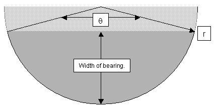
 This picture illustrates the meanings of some of the
variables related to the side bearings. The dark region represents
the actual side bearing. The lighter gray area is the piece of a
semicircle one would remove to make it into a side bearing. There are
many times when it was important to think of the side bearing related
to how things would have worked if I were using a full semicircle. The
following variables and equations were also used to calculate bearing
size:
x = Thickness of Formica
L = Length of dip in rocker box
r = radius of bearings
D = Dip in rocker box
θ = Angle covered by side bearing.
s = Angle of separation between Teflon pads

L = (sin(s/2)) * (r + x) * 2

D = (1 - cos(s/2)) * (r + x)
θ = s + 90 degrees (to go from zenith to horizon)
Here are some general notes from Kriege I kept in mind during the
design process:
- 22" side bearing diameter = 11" radius (pg 189).
- s = 70 degrees between Teflon pads (pg 201, 249, 255).
- Make the bearings 1 1/8" thick - I used 1" anyway and
have had no issues with bearing stiffness.
- Instructions for how to mount the side bearings to the rocker box
are on page 202.
- Large bearing radius makes it harder to move in the wind and
better star tracking (pg 247).
- Large angle between Teflon pads ("s") makes the scope
harder to move, a smaller angle makes it easier to move (pg 249).
Note the symmetry of the last two items on this list. I was able
to move the Teflon pads closer together to balance out the loss of
friction caused by making my bearing radius larger than suggested.
I made my bearings out of wood left over after I cut my ground
board out of the half sheets of 1/4" and 3/4" Baltic Birch I
glued together to make it an inch thick. The resulting pieces were
11" wide so I wanted to figure out the largest radius I would
have available to me for various spacings of the Teflon pads - and
corresponding values of θ.
Max θ/2 = ArcCos(1 - 11"/r)
From this I generated the following table of maximum radius values
based on various values of θ.
| θ | Maximum "r" |
|---|
| 160 degrees | 13.31" |
| 155 degrees | 14.03" |
| 150 degrees | 14.84" |
| 145 degrees | 15.73" |
One of the nice things about the design of this scope was that I
could correct balance issues by tuning the size of the side bearings.
Remember that the point that the scope is balanced on is at the
center point of the circles the bearings are cut from. If the center
of gravity of the scope is not at that center point, then the scope
will be top or bottom heavy and tend to tip over.
Because the bearings had to attach to the mirror cell, the bottom
edge of the bearings was going to be near the bottom of the mirror
cell. This means that as I made the diameter of the side bearings
larger, the center point of the bearings and hence the center of
gravity (CG) is pushed up towards the secondary cage and the scope
becomes more bottom heavy. This in turn meant that before I could cut
the side bearings, I needed to finish work on the mirror cell and
secondary cage so I knew how much each end would weigh. See the
design spreadsheet for more
information on how I calculated the center of gravity and from it the
bearing sizes.
I was able to make the bearings slightly smaller (and lighter) by
mounting them 3/4" above the bottom of the mirror cell. This
pushed up the CG, making the bearings in effect 3/4" larger in
radius for the purposes of CG calculations. I wasn't able to push the
bearings up any further though or the mirror cell wouldn't clear the
bottom of the rocker box as the scope rocked up or down. More
specifically, it wouldn't clear the top of the azimuth encoder for the
digital setting circles.
The scope was made as light as is reasonably possible. Special
attention was paid to making the top end light of course. The
bearings are also slightly bigger than they should be to make the
scope slightly tail heavy. This means that extra weight may be added
to the front of the scope in the future if necessary. By design, the
balance allows the use of a Paracor and 31mm Nagler at the same
time.
In the field, small bags of lead shot are used to tune the balance.
There's sufficient friction in the bearings that tipping doesn't
become a problem as long as I am within a pound or so of the proper
weight on the cage end. There is also enough friction to prevent the
scope from tipping upwards on its own as I am changing eyepieces.
In the future if a new toy causes the scope to become top heavy,
two fixes are available. The first would be to use springs to pull
the scope back into balance. The other, rather brute force method,
is to lug around 5 pounds of weight to put on the back end of the
scope to balance out each pound of weight stuck on the front.
The original plans for the rocker bearings included a brace between
the bearings to keep them from racking when the scope is turned. Del
told me one wouldn't be needed though and final assembly most
definitely proved him right. There is zero wobble.
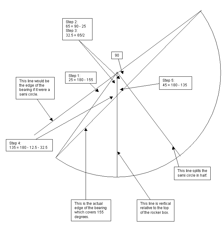
It is a mathematical coincidence that my side bearings are mounted
at a 45 degree angle. In the final design, the bearing pads are 65
degrees apart. That meant that my side bearings covered 90+65=155
degrees - or 25 degrees less than 180 degrees. Everything else more
or less follows from there. My original, incorrect math had them at a
different angle. Fortunately the error was so large that it was
evident in the shop before we started cutting. Of course cutting had
to halt while I worked out the right angle. Here's how I did it.

- Calculate the angle that is the difference between the arc covered
by the half circle and the arc covered by the bearing. In this case,
it is 25 degrees.
- The next step is to subtract those 25 degrees from the right angle
formed by the edge of the semicircle and its perpendicular. This not
too surprisingly is 65 degrees or the angle between the bearing
pads.
- The key insight was realizing that the 65 degrees in the previous
step corresponds to the telescope essentially pointing straight up.
The remaining 90 degrees is the angle the scope has to rotate from
pointing at the zenith to the horizon. Therefore the line bisecting
the 65 degree angle is vertical relative to the ground. We are now
only two geometry tricks away from the answer.
- The first trick is that the interior angles of a triangle add up
to 180 degrees. We know that one of these angles is 65/2 = 32.5
degrees. The other angle is half of the 25 degrees = 12.5 degrees.
This means that the angle pointed to is 180 - 32.5 - 12.5 = 135.
- And finally we use the trick that the angles on one side of a line
also add up to 180 degrees. So 180 - 135 = 45 degrees. Thus the side
of the bearing is 45 degrees from perpendicular.
Back to the Miatascope home page.
Last updated 1/12/06
 This picture illustrates the meanings of some of the
variables related to the side bearings. The dark region represents
the actual side bearing. The lighter gray area is the piece of a
semicircle one would remove to make it into a side bearing. There are
many times when it was important to think of the side bearing related
to how things would have worked if I were using a full semicircle. The
following variables and equations were also used to calculate bearing
size: