Mirror Cell/Mirror Box
Mirror support
I didn't see a mirror cell support in Kriege and Berry that looked
exactly like what I wanted. So I went off and found Plop
which looks to me like the latest generation of mirror cell design
software available on the web. It certainly takes some pretty subtle
factors into account in its design process.
The design it suggested was as follows:
As one would expect, the three triangular support pads are mounted
at 0, 120 and 240 degrees.
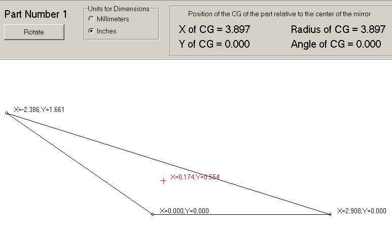
Plop generated this diagram of what the triangles should look
like: 
In this diagram, the point at (0,0) is the one that corresponds to
the 0/120/240 degree angle. The other two points will be at +/- 33.5
degrees from that angle.
The diagram also indicates that the CG (center of gravity)
marked by the red "+"for each triangle should be 3.897"
from the center of the mirror.
Kriege and Berry recommend using felt furniture pads (like the
kind used to protect hard wood floors) as the contacts between the
mirror and the mirror cell. So when I cut the triangles, I made them
about a 1/2" bigger all around to accommodate the 1" diameter
pads. This rounded the corners of the triangles into circular arcs
with the points specified by Plop as the arc centers.
This mirror cell design is claimed by Plop to have the following
errors:
- 9.95e-06 mm P-V (Peak-Valley) error
- 1.62e-06 mm RMS (Root Mean Square) error
A long (red) wavelength of light is approximately 7.5e-04mm. So
errors in the mirror surface due to the mirror cell design should be
less than 1/70th of a wave P-V and 1/430th of a wave RMS. If only a
mirror could be ground to those tolerances...
I am barely able to cut material reliably to one full decimal
place. So when Plop showed results accurate to 3 or 4 decimal places
I was worried that I would have a theoretical marvel that in the real
world was little better than a wet noodle once I built it. Playing
with the parameters in Plop to introduce some error though indicated
that a very acceptable mirror cell would still be built even with my
limited skills. The fact that the felt pads are soft areas 1" in
diameter rather than mathematical points is of great comfort to me as
well. I wouldn't be at all surprised to see that I could be off by as
much as 1/4" on some dimension and still produce a perfectly
acceptable mirror support.
During construction I became worried that the triangles Plop
suggested were too obtuse and cut new triangles based on the output
from Cell. After trading e-mail with Plop's author (who was very
helpful), I am convinced that my fears were unfounded. By the time I
found that out though I had already made and installed triangles based
on output from Cell.
Mirror box
Every 1/4" saved was worth extra effort to get. So the mirror
cell became a bit taller than originally planned so that it could also
make double as the mirror box. This change made the rocker box
3/4" smaller all around.

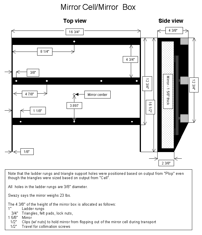
The diagram above shows the dimensions of the metal work that was
done for the mirror cell. The positions of the holes drilled for the
support triangles were taken from Kriege and Berry or the output of
Cell as would be relevant.
Because these diagrams are based on my notes, there are a few
mistakes. The ones I have found but was not able to correct are
mentioned in the errors section. The page
numbers referenced in the diagrams reference the page the topic was
discussed in Kriege and Berry by the way.
Back to the Miatascope home page.
Last updated 1/12/06

